


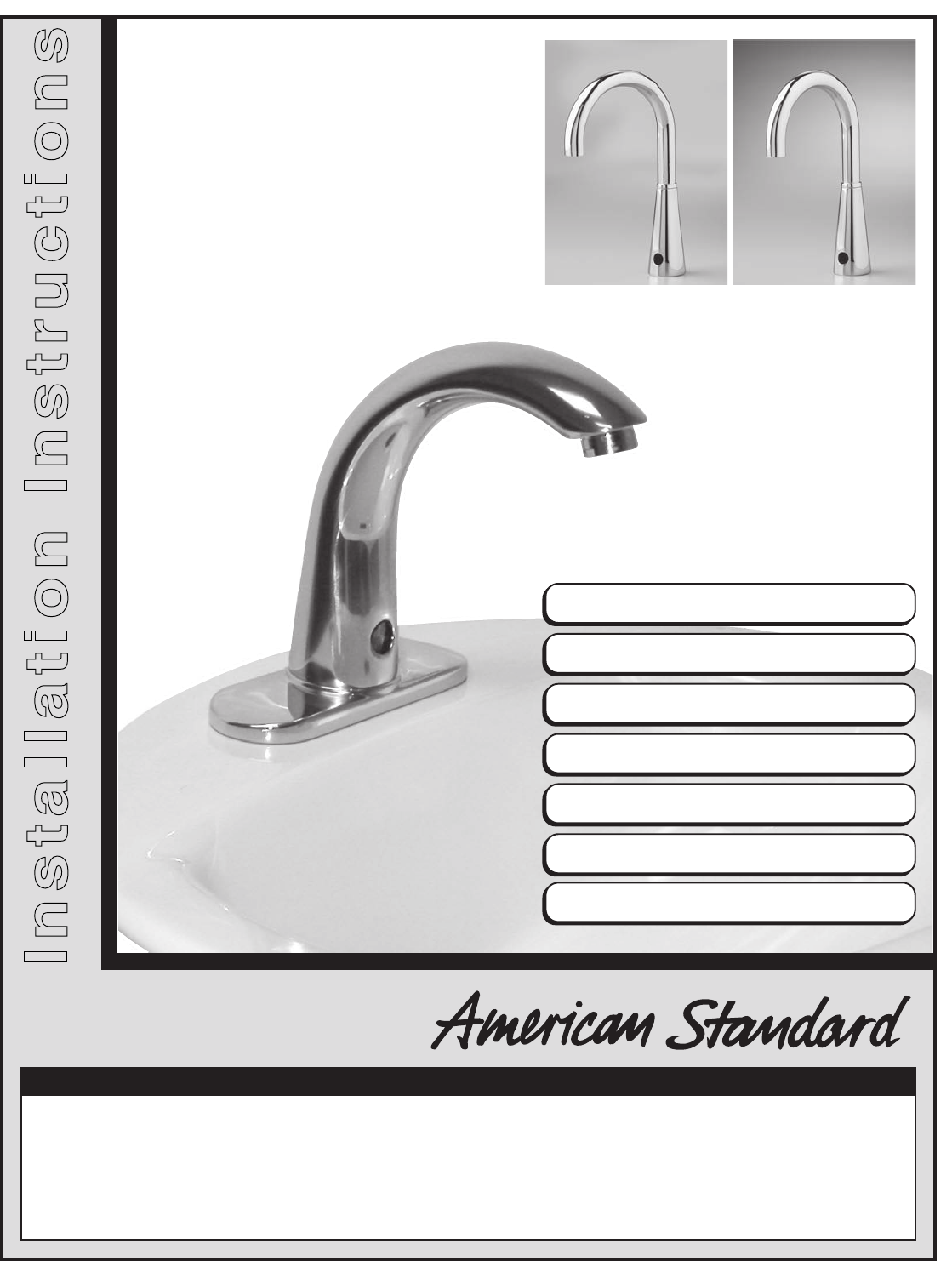
Installation Instructions
(In Toronto Area only: 1-905-3061093)
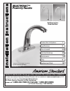
SELECTRONIC™
Proximity Faucets
Certified to comply with ASME A112.18.1M
© 2005 American Standard
To learn more about American Standard Faucets visit our website at: www.us.amstd.com or U.S.
customer's e-mail us at: faucetsupport@amstd.com
For Parts, Service, Warranty or other Assistance,
please call 1-800-442-1902 (In Canada: 1-800-387-0369)
NOTE TO INSTALLER: Please give this manual to the customer after installation.
(In Toronto Area only: 1-905-3061093)
Product No.'s & Options
Specifications
How to Install
Electrical Hook-up
Maintenance
FAQ,s
Replacement Parts
Cast Spout and two
Goose Neck Sizes
1
2
2-3
4-6
7-8
9
10
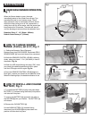
5c. 10 ft. Extension Wire (for 6057 series)
6. Circuit board
7. 4" Deck plate ( optional must be ordered separately)
8. 8" Deck plate ( optional must be ordered separately)
9. Mixing Valve ( optional must be ordered separately)
10. Key for vandal resistant aerator
1. Selectronic Spout Assembly
2. Mounting Kit
3. Electrical Enclosure
4. Supply Hose
5a. DC Power Supply (for 6055 series)
5b. AC Power Supply (for 6056 series)
All American Standard Faucets Are Water Tested At Our Factory.
Some Residual Water May Remain In The Faucet During Shipping.
Thank you for selecting American-Standard...the benchmark of fine quality for over 100 years. To
ensure that your installation proceeds smoothly--please read these instructions carefully before you
begin.
UNPACKING
1
605P400
605P800
605XTMV
6055.102
6055.105
PRODUCT No.s PRODUCT No.s PRODUCT No.s
6056.102
6056.105
6057.102
6057.105
6055.153
6055.155
6056.153
6056.155
6057.153
6057.155
6055.163
6055.165
6056.163
6056.165
6057.163
6057.165
1
10
2
3
5
6
7
8
9
4
Deck Plate Mixing ValveB a s e P r o d u c t
Cast Spout 5-1/4" GN Spout 6" GN Spout
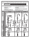
How to order the Selectronic Product
1. Choose Power Supply
2. Choose Desired Spout
• Single Hole Sink
• Single Inlet
• 1 and 3 Hole Sinks
• Single Inlet
• 1 and 3 Hole Sinks
• Hot and Cold Inlets
Base Product Deck Plate (optional) Mixing Valve (optional)
M968809 Rev.1.2
TOOLS REQUIRED; Fig. 2
Fig. 2
1 Channel Locks
2 Adjustable Wrench
3 Plumbers' Putty or Caulking
4 Phillips Screwdriver
5 Flat Blade Screwdriver
6 Electric Drill & 1/4" Drill Bit
7 Tape Measure
1
2
3
4
5
6
7
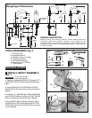
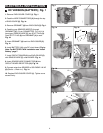
INSTALL SPOUT ASSEMBLY;
Fig. 1
INSTALLATION
CAUTION
Turn off hot and cold water
supplies before beginning
2
10'
1
Fig. 1
114mm
(4-1/2)
500mm
(20")
1524mm
(60)
381mm
(15)
3/8" COMP.
131mm
(5-1/8)
32mm (1-1/4)
125mm
(4-7/8)
81mm
(3-3/16)
49mm
(2)
141mm
(5-1/2)
11-1/8"
(284mm)
6-1/8"
(155mm)
MOUNTING
SURFACE
381mm
(15)
381mm
(15)
49mm
(2)
49mm
(2)
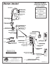
Roughing-in Dimensions
5-1/8"
(130mm)
7"
(179mm)
9-3/4"
(248mm)
6-1/8"
(155mm)
GENERAL DESCRIPTION:
Electronic faucet with proximity operation. Vandal resistant solid brass
construction single post mounting. Operates on DC (battery) or AC
permanent power. In-line strainer for solenoid is integral. Single inlet 3/8
compression, built-in checks, and flexible stainless steel 15" reach inlet hose
for spout connection.
1. (Optional) Assemble DECK PLATE (1) and PUTTY
PLATE (2) to FAUCET BODY (3) with SCREW (4).
Fig. 1.
2. Insert WIRES (5), FLEX HOSE (6) and SPOUT
SHANK (7) through center hole of mounting surface.
Fig. 1a.
3. Assemble "C" WASHER (8), STAR WASHER (9)
and LOCKNUT (10) onto threads of SPOUT SHANK
(7) from underside of mounting surface. Fig. 1b.
4. Align FAUCET (3) and tighten LOCKNUT (10). If
using DECK PLATE (1) hand tighten DECK PLATE
SPIN NUTS (11) to secure FAUCET (3) to mounting
surface. Fig. 1b.
10
11
Fig. 1a
Fig. 1b
9
5
7
7
6
8
3
1
1
2
2
Fig. 1
4
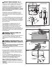
Fig. 2
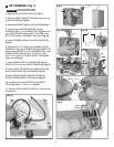
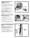
1. Determine location of ENCLOSURE (1). It must be
located with-in the 14" (356mm) by 21" (533mm)
shaded area shown in Figure 2 in order for electrical
connections from the spout assembly to be made.
NOTE: ENCLOSURE SUPPLY HOSE is 20". Distance
between wall supply and ENCLOSURE (1) must be
taken into consideration.
2. Remove 4 screws from COVER (2) and pull off
COVER (2). Hold the ENCLOSURE (1) in desired
location and mark the four mounting hole locations as
shown. Fig. 2.
3. The ENCLOSURE (1) works best if secured to a wall
stud or cross brace within the wall, using the SCREWS
(3) supplied. If the ENCLOSURE (1) is to be installed on
a tile or plaster wall the ANCHORS (4) and SCREWS
(3) should be used.
4. For installations on drywall or tiled walls; use
ANCHORS (4) and SCREWS (3) for securing
ENCLOSURE (1) to finished wall. Drill four 1/4" dia.
holes a minimum of 1-3/4" deep. Insert the four
ANCHORS (4) flush with face of the finished wall.
Align the ENCLOSURE (1) and Install the MOUNTING
SCREWS (3). Tighten to secure ENCLOSURE (1) to
mounting surface.
1524mm
(60)
14"
(356mm)
3-3/4"
(96mm)
2-3/4"
(71mm)
3"
(76mm)
21"
(mm)
2
4
3
1
1
1
20"
(500mm)
MOUNTING HOLES
SUPPLIES
WASTE
ENCLOSURE
MOUNTING
HOLES
LAVATORY RIM OR
MOUNTING SURFACE
3
NOTE: If using Mixing Valve (optional) See Sheet
#M968808 for installation instructions.
MOUNT ENCLOSURE; Fig. 2
2
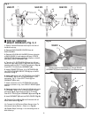
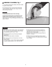
1. Connect SUPPLY NUT (1) from spout assembly to
nipple on top of ENCLOSURE (2). Tighten with
adjustable wrench to make a water tight connection.
Fig. 3.
NOTE; If using the optional Mixing Valve See Sheet
#M968808 for installation instructions.
CONNECT SPOUT HOSE TO
ENCLOSURE; Fig. 3
CONNECT WATER SUPPLY TO
ENCLOSURE AND WALL SUPPLY;
Fig. 4
3
Fig. 3
4
1
2
1
3
3
Fig. 4
2
1. Insert FIBER WASHER (4) into SUPPLY NUT (1) on
ENCLOSURE (2).
2. Connect SUPPLY NUT (1) on ENCLOSURE (2) to
FLEXIBLE SUPPLY HOSE (3). Tighten to make a
water tight connection. Use two wrenches to tighten if
necessary. Fig. 4.
3. Connect FLEXIBLE SUPPLY (3) directly to wall
supply. Connection on FLEXIBLE SUPPLY (3) is 3/8"
compression. Use adjustable wrench to tighten
connection. Do not over tighten. Fig. 4a.
Note: FLEXIBLE SUPPLY (3) measures 20" from the
bottom of the ENCLOSURE (1) base. If additional
supply length is required, installer must purchase parts
separately.
Important: If FLEXIBLE SUPPLY (3) is too long, loop to
avoid kinking.
COLD WATER OR
TEMPERED
WALL SUPPLY
Fig. 4a
4
1. Remove the fitting and loose items from the carton. The illustration below shows the fitting and all loose items
after they have been removed from the carton. Some items may be packaged partially assembled to other items.
1
605P400
605P800
605XTMV
6055.102
6055.105
PRODUCT No.s PRODUCT No.s PRODUCT No.s
6056.102
6056.105
6057.102
6057.105
6055.153
6055.155
6056.153
6056.155
6057.153
6057.155
6055.163
6055.165
6056.163
6056.165
6057.163
6057.165
1
10
2
3
5c
5a
5b
6
7
8
9
4
Deck Plate Mixing ValveB a s e P r o d u c t
Cast Spout 5-1/4" GN Spout 6" GN Spout