This manual contains instructions for installing your
American Sensors
TM
relay module. The relay module is ULC
listed as an accessory for use only with American Sensors
TM
interconnectable smoke alarms in the 470L, 670L and 770L
series, plus models SA360, SA379, ESA5011 and combina-
tion CO/Smoke alarm model COS2010.
WARNING:
This relay will not operate without continuous
AC power. Do not use with battery backup units.
CAUTION:
Do not interconnect Model No. CB100 to any
other manufacturer’s units.
RATING:
120VAC, 100mA
Use Your Relay Module For:
Sirens/Exit Signs/Bells
Warning Lights/Fire Doors/Exhaust Fans
Visual Indicators
CAUTION:
THE RELAY MODULE IS NOT TO BE USED
AS A METHOD OF EXTENDING THE MAXIMUM NUM-
BER OF SMOKE ALARMS PERMITTED IN MULTIPLE
STATION OPERATION. (REFER TO SMOKE ALARM
MANUAL FOR SPECIFIED MAXIMUM LIMIT.) EACH
RELAY MODULE REPLACES ONE SMOKE ALARM
LOAD IN AN INTERCONNECTED STRING. THEREFORE:
USE OF THE RELAY REDUCES THE MAXIMUM NUM-
BER OF INTERCONNECTED SMOKE ALARMS BY ONE.
RELAY MODULE MODEL NO. CB100
INSTRUCTION MANUAL
INSTALLATION INSTRUCTIONS
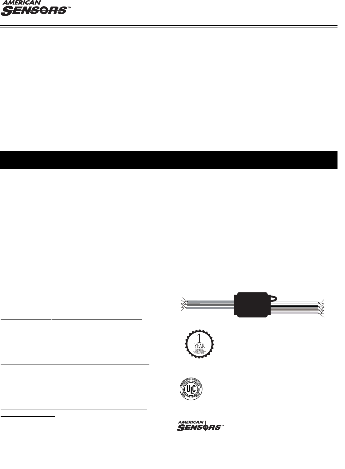
The CB100 relay module should be installed in a junction
box. All connections should be made by a qualified
electrician in accordance with the requirements of the
National Electric Code and/or any local codes having juris-
diction.
1. Turn off main power circuit.
2. Install and wire your compatible American Sensors
TM
smoke alarm as recommended in your smoke alarm
owner’s manual.
3. Connect the black wires of the relay module and the
smoke alarm to the black wire of the 120 VAC line.
4. Connect the interconnect wires as described below:
Your American Sensors
TM
CB100 relay module is easily con-
figured to allow it to operate for either a CO alarm condition
only, a smoke alarm condition only or for both CO and
smoke alarm conditions.
T
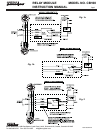
o Operate For A Smoke Alarm Condition Only:
See Fig. 1a and 1b on reverse.
Connect orange interconnect wire of the CB100 to the
orange interconnect wire of your smoke alarm (or to the
orange and brown wires of your CO/Smoke alarm).
T
o Operate Relay For A CO Alarm Condition Only:
See Fig 2 on reverse.
Connect brown interconnect wire of the CB100 to the
orange and brown wires of your co/smoke alarm and
orange wire of interconnected smoke alarms.
T
o Operate Relay For Both Smoke Alarm And CO
Alarm Conditions:
See Fig. 2 on reverse.
Open the green jumper wire on the CB100 and isolate
each end using a wire nut. Connect the brown intercon-
nect wire of the CB100 to the orange interconnect wire of
your smoke alarm and to the orange and brown wires of
your CO/Smoke alarm.
5. Connect the white wires of the relay module and the
smoke alarm to the white wire of the 120 VAC line.
6. Connect the auxiliary device to the relay module
contact leads as required. Both normally open and
normally closed contacts are available to control the
auxiliary device.
7. Cap any unused leads with a wire nut.
8. Insert the relay module into the junction box and install
the faceplate.
9. Apply power to the circuit and test the smoke alarm
and the auxiliary relay device for proper operation.
Dicon Global Inc.
88B East Beaver Creek Road, Unit 6,
Richmond Hill, Ontario, Canada L4B 4W2
Tel: 905-482-3720 Fax: 905-731-8267
info.diconglobal.com
This product is listed by
UNDERWRITER’S LABORATORIES OF
CANADA and Bears the Mark.
MODEL
MODEL
NO.
NO.
CB100
CB100
2502-A0032REVA
Page 1