


©American DJ® - www.americandj.com - Warp 250™ Instruction Manual Page 7 ©American DJ® - www.americandj.com - Warp 250™ Instruction Manual Page 8
Warp 250™ Set Up
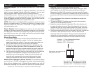
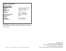
Data Cable Requirements (For DMX and Master/Slave Oper-
ation): Your unit excepts 3-pin XLR connector for data input and
data output (Figure 5) when linking for Master-Slave operation. If you
are making your own cables, be sure to use standard two conductor
shielded cable (This cable may be purchased at almost all pro sound
and lighting stores). Your cables should be made with a male and
female XLR connector on either end of the cable. Also remember that
DMX cable must be daisy chained and can not be split.
Warp 250™ Lamp Replacement
Caution: Always replace with the exact same type lamp and fuse,
unless otherwise specified by an authorized American DJ® technician.
Replacing with anything other than the specified part can damage the
unit and will void the manufactures warranty.
Warning: If, after replacing the lamp or fuse either one continues
to blow, STOP using the unit. Contact customer support for further
instructions, you may have to return the unit for servicing. Continuing
to use the unit may cause serious damage.
Lamp Replacement: Caution! Never attempt to change the lamp while
the fixture is plugged in. Always disconnect the main power and allow
the unit ample time to cool before attempting to replace the lamp.
Lamp replacement has been made simple by incorporating the use of
a removable lamp access panel that is retained by a thumb screw.
1. Be sure to follow the proper handling procedures that deal
with halogen lamps.
2. Remove the single thumb screw located on the top of the
unit.
3. Carefully remove the lamp socket access panel.
4. Carefully remove the old lamp and discard it in the trash.
5. Replace the lamp with an exact match and reassemble.
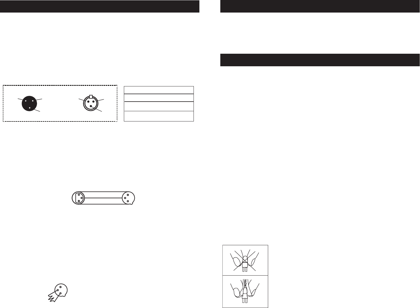
Halogen Lamp Warning:
This xture is tted with a halogen lamp which is
highly susceptible to damage if improperly han-
dled. Never touch the lamp with your bare ngers
as the oil from your hands will shorten lamp life.
Also, never move the xture until the lamp has
had ample time to cool. Remember, lamps are not
covered under warranty conditions.
This unit uses a protective breaker to protect the unit in the event of
power surges or fluctuations. To reset the breaker, push the breaker
button in until you hear it pop back in to place. If the breaker contin-
ues to pop, stop using the unit and contact customer support the unit
may require service.
Warp 250™ Reset Breaker
Figure 6
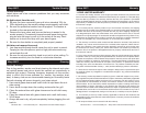
1 Ground
1 Ground
XLR Male Socket
XLR Pin Conguration
3 Hot
2 Cold
2 Cold
3 Hot
XLR Female Socket
Pin 3 = Data True (positive)
Pin 2 = Data Compliment (negative)
Pin 1 = Ground
Notice: Be sure to follow gures 6 and 7 when making your own
cables. Do not use the ground lug on the XLR connector. Do not con-
nect the cable’s shield conductor to the ground lug or allow the shield
conductor to come in contact with the XLR’s outer casing. Grounding
the shield could cause a short circuit and erratic behavior.
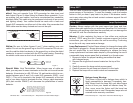
DMX512 IN
3-PIN XLR
SOUND
REMOTE
CONTROL
INPUT
POWER
INPUT OUTPUT
SOUND
REMOTE
CONTROL
INPUT
POWER
INPUT OUTPUT
SOUND
REMOTE
CONTROL
INPUT
POWER
INPUT OUTPUT
DMX512
DMX+,DMX-,COMMON
1
2
3
Termination reduces signal errors and
avoids signal transmission problems
and interference. It is always advisable
to connect a DMX terminal, (Resistance
120 Ohm 1/4 W) between PIN 2 (DMX-)
and PIN 3 (DMX +) of the last fixture.
1
2
3
1
2
3
DMX +
DMX -
COMMON
DMX512 OUT
3-PIN XLR
Figure 7
Special Note: Line Termination. When longer runs of cable are
used, you may need to use a terminator on the last unit to avoid erratic
behavior. A terminator is a 90-120 ohm 1/4 watt resistor which is con-
nected between pins 2 and 3 of a male XLR connector (DATA + and
DATA -). This unit is inserted in the female XLR connector of the last
unit in your daisy chain to terminate the line. Using a cable terminator
(ADJ part number ZDMX/T) will decrease the possibilities of erratic
behavior.
DMX512 IN
3-PIN XLR
SOUND
REMOTE
CONTROL
INPUT
POWER
INPUT OUTPUT
SOUND
REMOTE
CONTROL
INPUT
POWER
INPUT OUTPUT
SOUND
REMOTE
CONTROL
INPUT
POWER
INPUT OUTPUT
DMX512
DMX+,DMX-,COMMON
1
2
3
Termination reduces signal errors and
avoids signal transmission problems
and interference. It is always advisable
to connect a DMX terminal, (Resistance
120 Ohm 1/4 W) between PIN 2 (DMX-)
and PIN 3 (DMX +) of the last fixture.
1
2
3
1
2
3
DMX +
DMX -
COMMON
DMX512 OUT
3-PIN XLR
Figure 8