


27
MAINTENANCE OF YOUR WATER HEATER
3 Month Inspection
At least every 3 months, a visual inspection should be
made of the combustion air inlet as well as the exhaust and
water piping. Check the water heater for the following:
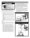
• Obstructions, damage, or deterioration in the venting
system. Make sure the exhaust and combustion air
supplies are not obstructed.
• Leaking or damaged water and gas piping.
• Presence of fl ammable or corrosive materials in the
installation area.
• Presence of combustible materials near the water
heater.
Important: Verify proper operation after servicing this water
heater.
Gas Valve
The gas valve on this water heater has been permanently
set at the factory for proper operation. No field adjustments
are needed and none should be performed.
Removing the Gas Valve
Removal and replacement of the gas regulator valve
involves the disconnection of gas piping and electrical
leads. This procedure must be performed by a qualified
service technician.
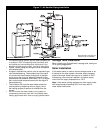
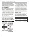
Important: When removing the gas valve, do not use a
pipe wrench or vise to grip the body. Do not apply any force
to the gas valve or the cast flange fitting on the inlet side
of the gas valve (see figure 25.) Such force may break or
crack these components.
1. Turn temperature dial counterclockwise to the lowest
setting and turn off electrical power to appliance.
2. Shut off the gas at the manual shut-off valve on the
gas supply line. See figure 19 for reference. Remove
the access door.
3. Disconnect the gas piping connection just outside
the base of the water heater . Note: Use a second
pipe wrench on the gas piping inside the skirt to avoid
cracking the gas valve or the flange fitting.
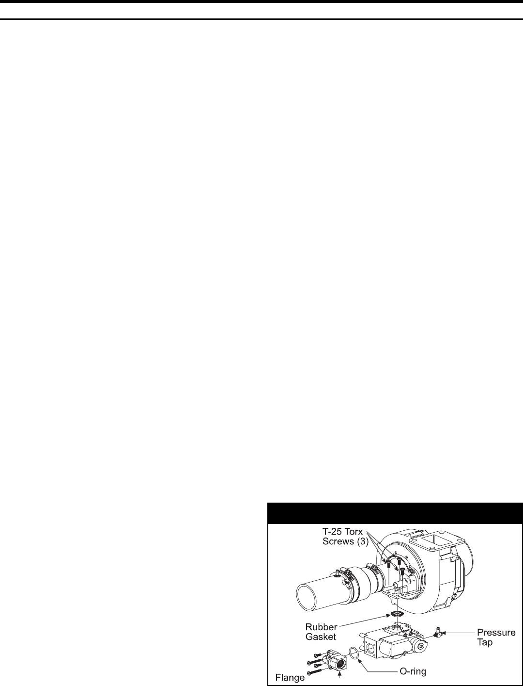
4. Remove the pressure tap from the gas valve (see
figure 25). The hose should not be disconnected.
5. Remove the Phillips head screw holding the electrical
plug and remove electrical plug from the gas valve.
6. Remove the three T-25 Torx head brass screws that
attach the gas valve to the venturi manifold, using
the T-25 Torx wrench supplied with the gas valve kit
(model VK8115V, part number 6903775.)
7. Remove the gas valve from the unit keeping the
rubber gasket with the gas valve .
8. Remove the flange from the gas inlet side of the valve
by removing the four (4) attachment screws.
Figure 25
Replacing the Gas Valve
Important: The rubber gasket that seals the gas valve to
the venturi manifold must be used (previous gaskets may
be reused, if in good condition). Make sure the gasket is
properly inserted into the recess on the gas valve prior to
installation (see figure 25 for exact placement of the rubber
gasket).
1. Remove the O-ring from the flange (removed from the
old gas valve) and replace it with the one provided
in the gas valve kit (model VK8115V, part number
6903775.)
2. Reattach the elbow flange to the gas valve. Tighten all
four screws securely.
3. Place the three T-25 Torx screws through the proper
holes in the venturi manifold flange. See figure 25.
4. Properly install a new rubber gasket (provided) as
shown in figure 25.
5. Position the gas valve and start all three screws
(projecting downward from the venturi manifold) into
the gas valve. A T-25 Torx wrench has been provided
in the gas valve replacement kit (model VK8115V, part
number 6903775.)
Note: All three T-25 Torx screws must be properly tightened
to secure the seal between the gas valve and the venturi
manifold.
6. Reconnect the pressure tap to the port on the new gas
valve (see figure 25).
7. Reconnect the external gas supply line to the gas pip-
ing on the gas valve. Be sure to use approved Teflon
tape or pipe joint compound suitable for gas piping.
Note: Use a second pipe wrench on the gas piping inside
the skirt to avoid cracking the gas valve or the cast fitting.
8. Reconnect the electrical plug to the gas valve and
secure it with the screw provided.
9. Turn gas supply on and check for leaks. Use a chlo-
ride-free soap and water solution (bubbles forming
indicate a leak) or other approved method. All leaks
must be fixed immediately.
10. Be sure tank is completely filled with water before re-
storing power to the water heater. Follow operating
instructions on Page 25.
11. Ensure proper operation of the water heater, then rein-
stall the access door.
If additional information is required, contact the Product
Service and Support Group at 1-800-456-9805.