


15
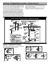
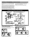
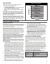
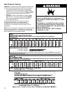
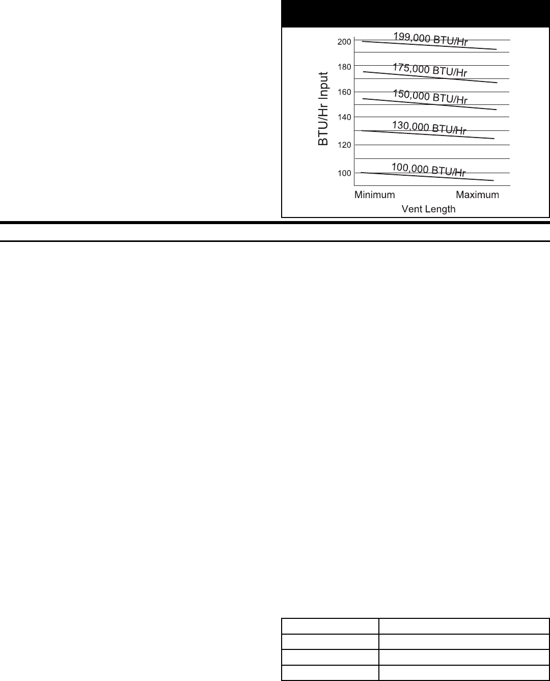
Figure 14: Input Graph
Gas Input Rate
The gas input rate of this water heater is affected by
several environmental factors such as:
• The heating value of the gas
• The air and gas densities (which vary widely due to baro-
metric pressure and temperature changes)
• Venting installations (pipe diameter, length and fittings)
• Altitude
When measuring the input rate these factors should be
incorporated into the calculations. Also measure the gas
consumption over a sufficiently long time to obtain an
accurate gas consumption rate (e.g. 3-5 minutes, not one
revolution of the meter needle).
Long vents and each additional elbow, inherently reduce
the gas input rate due to increased resistance to moving
combustion air and flue gases. The approximate maximum/
minimum input for the 100k, 130k, 150k, 175k, and the
199k models is shown in figure 14.
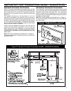
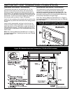
WATER PIPING SYSTEM
Piping Installation
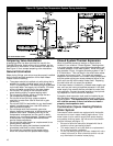
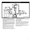
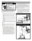
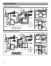
Piping, fi ttings, and valves should be installed according to
the installation drawing (fi gure 15). If the indoor installation
area is subject to freezing temperatures, the water piping
must be protected by insulation.
Water supply pressure should not exceed 80% of the
working pressure of the water heater. The working pressure
is stated on the water heater’s data plate. If this occurs a
pressure reducing valve with a bypass should be installed
in the cold water inlet line to the entire system. This should
be placed on the supply to the entire structure in order to
maintain equal hot and cold water pressures.
Important: Heat cannot be applied to the water fi ttings
on the heater as they may contain nonmetallic parts.
If solder connections are used, solder the pipe to the
adapter before attaching the adapter to the hot and
cold water fi ttings.
Important: Do not install this water heater with iron or
galvanized piping. Use brass caps on all unused inlet/
outlet connections.
1. Install the water piping and fi ttings as shown in fi gure
15. Note: If state or local codes require, install a vacu-
um relief valve per the manufactures instructions in the
cold water supply line. Connect the cold water supply
(50 gal. and below use 1” NPT, 100 gal. use 1-1/2”
NPT) to the fi tting marked “COLD INLET”. Do not turn
the cold water nipple. The mark should remain along
the top side of the nipple (34 & 50 gal models only.)
Connect the hot water supply (50 gal. and below use
1” NPT, 100 gal. use 1-1/2” NPT) to the fi tting marked
“HOT OUTLET”.
2. Always use a suitable grade of joint compound and be
certain that all fi ttings are tightened properly.
3. The installation of unions in both the hot and cold water
supply lines is recommended for ease of removing the
water heater for service or replacement.
4. If installing the water heater in a closed water system,
install an expansion tank in the cold water line as speci-
fi ed under “Closed System/Thermal Expansion” (Page
16).
5. Install a shut-off valve in the cold water inlet line. It
should be located close to the water heater and be
easily accessible. Know the location of this valve and
how to shut off the water to the heater.
6. The Polaris
®
gas water heater is shipped with a fac-
tory-installed Temperature and Pressure Relief Valve.
Install a discharge line in the opening in the T & P valve
(see instructions on Page 18).
7. After piping has been properly connected to the water
heater, remove the aerator at the nearest hot water
faucet. Open the hot water faucet and allow the tank
to completely fi ll with water. (To prevent damage to
the unit, DO NOT connect power until the tank is
COMPLETELY FILLED). To purge the lines of any
excess air, keep the hot water faucet open for 3 min-
utes after a constant fl ow of water is obtained. Close
the faucet and check all connections for leaks.
Corrosion and Water Quality
Water quality will vary from location to location and may
contain contaminates that may reduce the life or perfor-
mance of the water heater. To test for contaminates a
water quality test kit is available, reference part number
6903791.
Contaminates which can reduce the life or performance
of the water heater if present in high quantities include
those which contribute to hardness (dissolved minerals
such as sodium, calcium and magnesium); plus chlorides
and sulfates. Additionally, water that is too acidic or basic
(measured as pH) can reduce the life of the water heater.
Water treatment systems (such as water softeners for
hardness) should be used and maintained properly if the
contaminate levels exceed the following:
Warranty is void in applications which exceed the
water quality requirements listed below.
Total Hardness: 12 grains per gal. (205 mg/liter) max.
Chloride: 200 mg/liter max.
pH: 6.5-8.0
Alkalinity: 200 mg/liter max.