


29
S
TART
-
UP
P
ROCEDURE
AND
A
DJUSTMENT
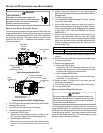
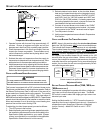
3. Outlet pressure tap connections:
a. Honeywell VR9205 valve: Remove the outlet pressure
boss plug. Install an 1/8" NPT hose barb fitting into
the outlet pressure tap.
b. White-Rodgers 36G54 valve: Back outlet pressure test
screw (inlet/outlet pressure boss) out one turn
(counterclockwise, not more than one turn).
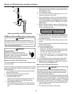
4. Attach a hose and manometer to the outlet pressure
barb fitting (Honeywell valve) or outlet pressure boss
(White-Rodgers valve).
5. Turn ON the gas supply.
6. Turn on power and close thermostat “R” and “W1”
contacts to provide a call for low stage heat.
7. Measure the gas manifold pressure with burners firing.
Adjust manifold pressure using the Manifold Gas
Pressure table shown below.
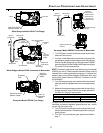
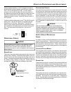
8. Remove regulator cover screw from the low (LO) outlet
pressure regulator adjust tower and turn screw clockwise
to increase pressure or counterclockwise to decrease
pressure. Replace regulator cover screw.
9. Close thermostat “R” and “W2” contacts to provide a
call for high stage heat.
10. Remove regulator cover screw from the high (HI) outlet
pressure regulator adjust tower and turn screw clockwise
to increase pressure or counterclockwise to decrease
pressure. Replace regulator cover screw.
11. Turn off all electrical power and gas supply to the system.
12. Remove the manometer hose from the hose barb fitting
or outlet pressure boss.
13. Replace outlet pressure tap:
a. Honeywell VR9205 valve: Remove the 1/8" NPT hose
barb fitting from the outlet pressure tap. Replace the
outlet pressure boss plug and seal with a high quality
thread sealer.
b. White-Rodgers 36G54 valve: Turn outlet pressure test
screw in to seal pressure port (clockwise, 7 in-lb
minimum).
14. Turn on electrical power and gas supply to the system.
15. Close thermostat contacts “R” and “W1/W2” to energize
the valve.
Using a leak detection solution or soap suds, check for leaks
at outlet pressure boss plug (Honeywell valve) or screw (White-
Rodgers valve). Bubbles forming indicate a leak. SHUT OFF
GAS AND REPAIR ALL LEAKS IMMEDIATELY!
NOTE: For gas to gas conversion, consult your dealer for
appropriate conversion.
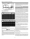
Range Nominal
Natural Low Stage 1.6 - 2.2" w.c. 1.9" w .c.
High Stage 3.2 - 3.8" w .c. 3.5" w .c.
Propane Low Stage 5.7 - 6.3" w .c. 6.0" w.c.
High Stage 9.7 - 10.3" w.c
.
10.0" w.c.
Manifold Gas Pressure
Gas
GAS I NPUT R ATE M EASUREMENT (NATURAL G AS O NLY)
The gas input rate to the furnace must never be greater than
that specified on the unit rating plate. To measure natural gas
input using the gas meter, use the following procedure.
1. Turn OFF the gas supply to all other gas-burning
appliances except the furnace.
2. While the furnace is operating, time and record one
complete revolution of the smallest gas meter dial.
3. Calculate the number of seconds per cubic foot (sec/ ft
3
)
of gas being delivered to the furnace. If the dial is a one
cubic foot dial, divide the number of seconds recorded in
step 2 by one. If the dial is a two cubic foot dial, divide
the number of seconds recorded in step 2 by two.
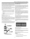
4. Calculate the furnace input in BTUs per hour (BTU/ hr).
Input equals the installation’s gas heating value multiplied
by a conversion factor (hours to seconds), divided by
the number of seconds per cubic foot. The measured
input must not be greater than the input indicated on the
unit rating plate.
EXAMPLE:
Installation’s gas heating (HTG) value: 1,000 BTU/ft
3
(Obtained from gas supplier)
Installation’s seconds per cubic foot: 34 sec/ ft
3
Conversion Factor (hours to seconds): 3600 sec/hr
Input = (Htg. value x 3600) ÷ seconds per cubic foot
Input = (1,000 BTU/ft
3
x 3600 sec/hr) ÷ 34 sec/ ft
3
Input = 106,000 BTU/hr
This measured input must not be greater than the input
indicated on the unit rating plate.
5. Turn ON gas and relight appliances turned off in step 1.
Ensure all the appliances are functioning properly and
that all pilot burners are operating.
TEMPERATURE R ISE
Air temperature rise is the temperature difference between supply
and return air. The proper amount of temperature rise is usu-
ally obtained when the unit is operated at the rated input with
the “as shipped” blower speed. If the correct amount of tem-
perature rise is not obtained, it may be necessary to change
the blower speed.
An incorrect temperature rise can cause condensing in or over-
heating of the heat exchanger. Determine and adjust the tem-
perature rise as follows. The temperature rise must be within
the range specified on the rating plate or Specification Sheet
applicable to your model. (Please contact your distributor or
our website for the applicable Specification Sheet referred to
in this manual.)