


28
S
TART
-
UP
P
ROCEDURE
AND
A
DJUSTMENT
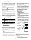
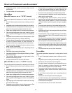
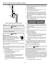
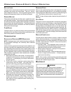
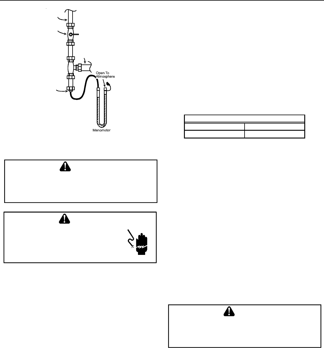
Gas Line
Gas
Shutoff
Valve
Gas Line
To Furnace
Drip Leg Cap
With Fitting
Manometer Hose
Measuring Inlet Gas Pressure (Alt. Method)
GAS M ANIFOLD P RESSURE M EASUREMENT AND ADJUSTMENT
T
O
PREVENT
UNRELIABLE
OPERATION
OR
EQUIPMENT
DAMAGE
,
THE
GAS
MANIFOLD
PRESSURE
MUST
BE
AS
SPECIFIED
ON
THE
UNIT
RATING
PLATE
.O
NLY
MINOR
ADJUSTMENTS
SHOULD
BE
MADE
BY
ADJUSTING
THE
GAS
VALVE
PRESSURE
REGULATOR
.
CAUTION
HIGHVOL TAGE!
D
ISCONNECT
ALL
POWER
BEFORE
SERVICING
OR
INSTALLING
THIS
UNIT
.M
ULTIPLE
POWER
SOURCES
MAY
BE
PRESENT
.F
AILURE
TO
DO
SO
MAY
CAUSE
PROPERTY
DAMAGE
,
PERSONAL
INJURY
OR
DEATH
.
WARNING
MODELS USING SINGLE STAGE GAS VALVES
This valve is shipped from the factory with the regulator preset
(see control label).
Consult the appliance rating plate to ensure burner manifold
pressure is as specified. If another outlet pressure is required,
follow these steps.
1. Turn OFF gas to furnace at the manual gas shutoff valve
external to the furnace.
2. Turn OFF all electrical power to the system.
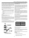
3. Outlet pressure tap connections:
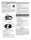
a. Honeywell VR8215 valve:
Remove the outlet pressure boss plug. Install an 1/8”
NPT hose barb fitting into the outlet pressure tap.
b. White-Rodgers 36G22 valve:
Back outlet pressure test screw (outlet pressure boss)
out one turn (counterclockwise, not more than one
turn).
4. Attach a hose and manometer to the outlet pressure
barb fitting (Honeywell valve) or outlet pressure boss
(White-Rodgers valve).
5. Turn ON the gas supply.
6. Turn ON power and close thermostat “R” and “W”
contacts to provide a call for heat.
7. Using a leak detection solution or soap suds, check for
leaks at outlet pressure boss plug (Honeywell valve) or
screw (White-Rodgers valve). Bubbles forming indicate
a leak. SHUT OFF GAS AND REPAIR ALL LEAKS
IMMEDIATELY!
8. Measure the gas manifold pressure with burners firing.
Adjust manifold pressure using the Manifold Gas
Pressure table shown below.
Manifold Gas Pressure
Natural Gas 3.5" w.c.
Propane Gas 10.0" w.c.
9. Remove regulator cover screw from the outlet pressure
regulator and turn screw clockwise to increase pressure
or counterclockwise to decrease pressure. Replace
regulator cover screw.
10. Turn OFF all electrical power and gas supply to the
system.
11. Remove the manometer hose from the hose barb fitting
or outlet pressure boss.
12. Replace outlet pressure tap:
a. Honeywell VR8215 valve:
Remove the 1/8” NPT hose barb fitting from the outlet
pressure tap. Replace the outlet pressure boss plug
and seal with a high quality thread sealer.
b. White-Rodgers 36G22 valve: Turn outlet pressure test
screw in to seal pressure port (clockwise, 7 in-lb
minimum).
13. Turn ON electrical power and gas supply to the system.
14. Close thermostat contacts to provide a call for heat.
15. Retest for leaks. If bubbles form, SHUT OFF GAS AND
REPAIR ALL LEAKS IMMEDIATELY!
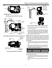
MODELS USING TWO STAGE GAS VALVES
T
O
PREVEN T
UNRELIABLE
OPERATION
OR
EQUIPMENT
DAMAGE
,
THE
GAS
MANIFOLD
PRESSURE
MUST
BE
AS
SPECIFIED
ON
THE
UNIT
RATING
PLATE
.O
NLY
MINOR
ADJUSTMENTS
SHOULD
BE
MADE
BY
ADJUSTING
THE
GAS
VALVE
PRESSURE
REGULATOR
.
CAUTION
Only small variations in gas pressure should be made by ad-
justing the gas valve pressure regulator. The manifold pressure
must be measured with the burners operating. To measure
and adjust the manifold pressure, use the following procedure.
1. Turn OFF gas to furnace at the manual gas shutoff valve
external to the furnace.
2. Turn off all electrical power to the system.