


22
C
IRCULATING
A
IR
AND
F
ILTERS
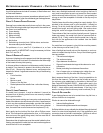
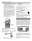
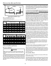
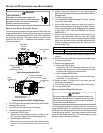
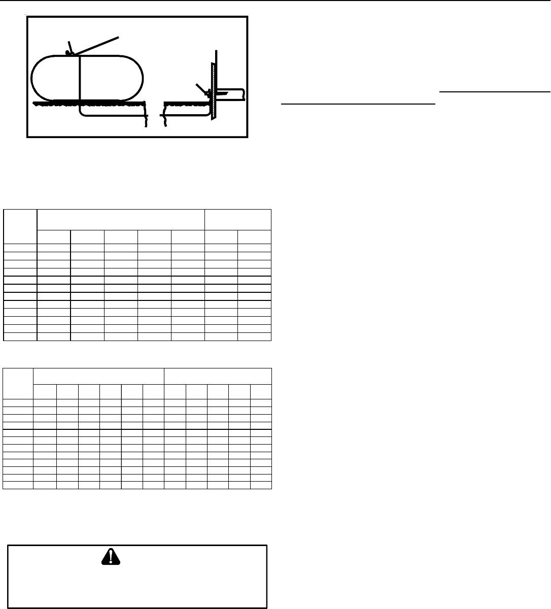
200 PSIG
Maximum
5 to 15 PSIG
(20 PSIG Max.)
Continuous
11" W.C.
Second Stage
Regulator
First Stage
Regulator
Propane Gas Installation (Typ.)
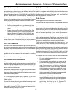
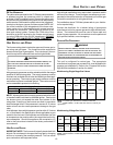
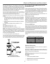
PROPANE G AS P IPING C HARTS
3/8" 1/2" 5/8" 3/4" 7/8" 1/2" 3/4"
10 730 1,700 3,200 5,300 8,300 3,200 7,500
20 500 1,100 2,200 3,700 5,800 2,200 4,200
30 400 920 2,000 2,900 4,700 1,800 4,000
40 370 850 1,700 2,700 4,100 1,600 3,700
50 330 770 1,500 2,400 3,700 1,500 3,400
60 300 700 1,300 2,200 3,300 1,300 310
80 260 610 1,200 1,900 2,900 1,200 2,600
100 220 540 1,000 1,700 2,600 1,000 2,300
125 200 490 900 1,400 2,300 900 2,100
150 190 430 830 1,300 2,100 830 1,900
175 170 400 780 1,200 1,900 770 1,700
200 160 380 730 1,100 1,800 720 1,500
Sizing Between First and Second Stage Regulator*
Maximum Propane Capacities listed are based on 2 psig pressure drop at 10 psig setting.
Capacities in 1,000 BTU/hour.
Nominal Pipe Size
Schedule 40
Tubing Size, O.D. Type L
Pipe or
Tubing
Length,
Feet
3/8" 1/2" 5/8" 3/4" 7/8" 1-1/8" 1/2" 3/4" 1" 1-1/4" 1-1/2"
10 39 92 199 329 501 935 275 567 1,071 2,205 3,307
20 26 62 131 216 346 630 189 393 732 1,496 2,299
30 21 50 107 181 277 500 152 315 590 1,212 1,858
40 19 41 90 145 233 427 129 267 504 1,039 1,559
50 18 37 79 131 198 376 114 237 448 913 1,417
60 16 35 72 121 187 340 103 217 409 834 1,275
80 13 29 62 104 155 289 89 185 346 724 1,066
100 11 26 55 90 138 255 78 162 307 630 976
125 10 24 48 81 122 224 69 146 275 567 866
150 9 21 43 72 109 202 63 132 252 511 787
200 8 19 39 66 100 187 54 112 209 439 665
250 8 17 36 60 93 172 48 100 185 390 590
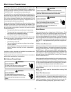
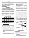
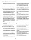
Pipe or
Tubing
Length,
Feet
Nominal Pipe Size
Schedule 40
Tubing Size, O.D. Type L
Sizing Between Second Stage and Appliance Regulator*
Maximum Propane Capacities listed are based on 2 psig pressure drop at 10 psig setting.
Capacities in 1,000 BTU/hour.
C
IRCULATING
A
IR
AND
F
ILTERS
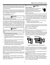
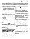
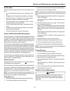
DUCTWORK - AIR F LOW
N
EVER
ALLOW
THE
PRODUC TS
OF
COMBUSTION
,
INCLUDING
CARBON
MONOXIDE
,
TO
ENTER
THE
RETURN
DUCT
WORK
OR
CIRCULATION
AIR
SUPPLY
.
WARNING
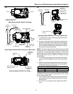
Duct systems and register sizes must be properly designed for
the CFM and external static pressure rating of the furnace.
Ductwork should be designed in accordance with the recom-
mended methods of “Air Conditioning Contractors of America”
Manual D.
A duct system must be installed in accordance with Standards
of the National Board of Fire Underwriters for the Installation of
Air Conditioning, Warm Air Heating and Ventilating Systems.
Pamphlets No. 90A and 90B.
A closed return duct system must be used, with the return duct
connected to the furnace. NOTE: Ductwork must never be
attached to the back of the furnace. For installations requiring
more than 1800 CFM, use a bottom return or two sided return.
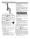
Supply and return connections to the furnace may be made
with flexible joints to reduce noise transmission. To prevent the
blower from interfering with combustion air or draft when a cen-
tral return is used, a connecting duct must be installed be-
tween the unit and the utility room wall. Furnace is shipped
with the top flanges in the flat position. Before installing a coil
or ducts, the flanges must be bent 90°. A room, closet, or
alcove must not be used as a return air chamber.
When the furnace is used in connection with a cooling unit, the
furnace should be installed in parallel with or on the upstream
side of the cooling unit to avoid condensation in the heating
element. With a parallel flow arrangement, the dampers or other
means used to control the flow of air must be adequate to
prevent chilled air from entering the furnace and, if manually
operated, must be equipped with means to prevent operation of
either unit unless the damper is in the full heat or cool position.
When the furnace is installed without a cooling coil, it is rec-
ommended that a removable access panel be provided in the
outlet air duct. This opening shall be accessible when the fur-
nace is installed and shall be of such a size that the heat
exchanger can be viewed for visual light inspection or such that
a sampling probe can be inserted into the airstream. The ac-
cess panel must be made to prevent air leaks when the furnace
is in operation.
NOTE: In a horizontal installation the air conditioning coil
must be adequately supported by proper brackets and
supports. Inadequate coil support can result in furnace cabinet
distortion and air leakage.
When the furnace is heating, the temperature of the return air
entering the furnace must be between 55°F and 100°F.
When a furnace is installed so that supply ducts carry air cir-
culated by the furnace to areas outside the space containing
the furnace, the return air shall also be handled by a duct sealed
to the furnace casing and terminating outside the space con-
taining the furnace.
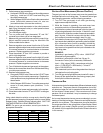
CHECKING D UCT S TATIC
Refer to your furnace rating plate for the maximum ESP (exter-
nal duct static) rating.
Total external static refers to everything external to the furnace
cabinet. Cooling coils, filters, ducts, grilles, registers must all
be considered when reading your total external static pres-
sure. The supply duct pressure must be read between the fur-