


4
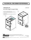
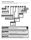
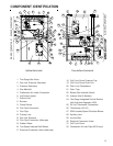
PRODUCT DESIGN
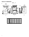
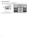
4. Installer must supply the following gas line fittings, de-
pending on which entrance is used:
Left -- Two 90° Elbows, one close nipple, straight pipe
Right -- Straight pipe to reach gas valve.
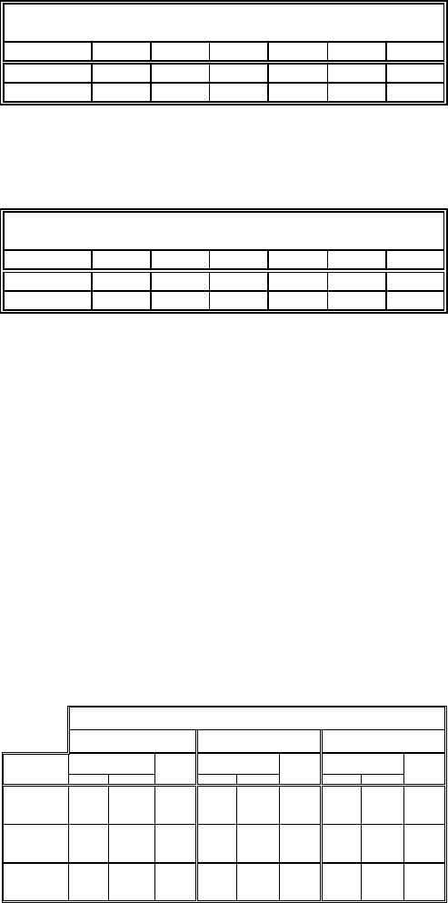
Accessibility Clearances (Minimum)
POSITION* FRONT SIDES REAR TOP FLUE FLOOR
Upflow30010C
Horizontal36060C
*= All positioning is determined as installed unit is viewed from the front.
C= If placed on combustible floor, floor MUST be wood only.
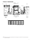
POSITION* FRONT SIDES REAR TOP FLUE FLOOR
Upflow30010NC
Horizontal36060C
*= All positioning is determined as installed unit is viewed from the front.
C= If placed on combustible floor, floor MUST be wood only.
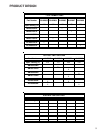
AMV9 MINIMUM CLEARANCES TO COMBUSTIBLE MATERIALS
(INCHES)
NC= For instalaltion on non-combustible floors only. A combustible
subbase must be used for installations on combustible flooring.
ACV9 MINIMUM CLEARANCES TO COMBUSTIBLE MATERIALS
(INCHES)
NC= For instalaltion on non-combustible floors only. A combustible
subbase must be used for installations on combustible flooring.
36" at front is required for servicing or cleaning.
Note: In all cases accessibility clearance shall take prece-
dence over clearances from the enclosure where accessi-
bility clearances are greater. All dimensions are given in
inches.
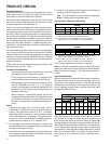
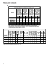
High Altitude Derate
When this furnace is installed at high altitude, the appropri-
ate High Altitude orifice kit must be installed. This is re-
quired due to the natural reduction in the density of both
the gas fuel and combustion air as altitude increases. The
kit will provide the proper design certified input rate within
the specified altitude range.
Natural Propane Natural Propane Natural Propane
AMV90453BX*
AMV90704CX*
No
Change
LPM-05*
#55 Orifice
No
Change
HANG13
#44
Orifice
HALP11
#56 Orifice
HAPS28
HANG14
#45
Orifice
HALP11
#56
Orifice
HAPS28
AMV90905DX*
AMV91155DX*
No
Change
LPM-05*
#55 Orifice
No
Change
HANG13
#44
Orifice
HALP11
#56
Orifice
HAPS29
HANG14
#45
Orifice
HALP11
#56
Orifice
HAPS29
ACV90704CX*
ACV90905DX*
No
Change
LPM-05*
#55 Orifice
No
Change
HANG13
#44
Orifice
HALP11
#56
Orifice
HAPS29
HANG14
#45
Orifice
HALP11
#56
Orifice
HAPS31
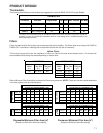
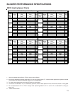
9,001 - 11,000 Feet
"STANDARD" and "HIGH ALTITUDE" KITS
Furnace
ID Blwr
Pressure
Switch
Gas Orifices
0 - 7,000 Feet
(Standard Altitude)
7,001 - 9,000 Feet
Gas Orifices
ID Blwr
Pressure
Switch
ID Blwr
Pressure
Switch
Gas Orifices
High altitude kits are purchased according to the installa-
tion altitude and usage of either natural or propane gas.
Refer to the chart above for a tabular listing of appropriate
altitude ranges and corresponding manufacturer’s high al-
titude Natural Gas and Propane Gas kits. For a tabular list-
ing of appropriate altitude ranges and corresponding
manufacturer's High Altitude Pressure Switch kits, refer to
either the Pressure Switch Trip Points & Usage Chart in
this manual or the Accessory Charts in Service Instruc-
tions.
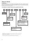
General Operation
The AMV9 and ACV9 furnaces are equipped with an elec-
tronic ignition device to light the burners and an induced
draft blower to exhaust combustion products.
An interlock switch prevents furnace operation if the blower
door is not in place. Keep the blower access doors in place
except for inspection and maintenance.
This furnace is also equipped with a self-diagnosing elec-
tronic control module. In the event a furnace component is
not operating properly, the control module LED will flash on
and off in a factory-programmed sequence, depending on
the problem encountered. This light can be viewed through
the observation window in the blower access door. Refer to
the Troubleshooting Chart for further explanation of the LED
codes and Abnormal Operation - Integrated Ignition Con-
trol section in the Service Instructions for an explanation of
the possible problem.
The rated heating capacity of the furnace should be greater
than or equal to the total heat loss of the area to be heated.
The total heat loss should be calculated by an approved
method or in accordance with “ASHRAE Guide” or “Manual
J-Load Calculations” published by the Air Conditioning Con-
tractors of America.
*Obtain from: American National Standards Institute 1430
Broadway New York, NY 10018
Location Considerations
• The furnace should be as centralized as is practical
with respect to the air distribution system.
• Do not install the furnace directly on carpeting, tile,
or combustible material other than wood flooring.
• When suspending the furnace from rafters or joists,
use 3/8" threaded rod and 2” x 2” x 1/8” angle as
shown in the Installation and Service Instructions. The
length of the rod will depend on the application and
clearance necessary.
• When installed in a residential garage, the furnace
must be positioned so the burners and ignition source
are located not less than 18 inches (457 mm) above
the floor and protected from physical damage by ve-
hicles.
Notes:
1. Installer must supply one or two PVC pipes: one for
combustion air (optional) and one for the flue outlet (re-
quired). Vent pipe must be either 2” or 3” in diameter,
depending upon furnace input, number of elbows, length
of run and installation (1 or 2 pipes). The optional Com-
bustion Air Pipe is dependent on installation/code re-
quirements and must be 2” or 3” diameter PVC.
2. Line voltage wiring can enter through the right or left
side of the furnace. Low voltage wiring can enter through
the right or left side of furnace.
3. Conversion kits for propane gas and high altitude natu-
ral and propane gas operation are available. See High
Altitude Derate chart for details.