


Professional Spacesaver
Tools Required: Phillips screwdriver, drill with
1
/16" bit.
Assembly Instructions
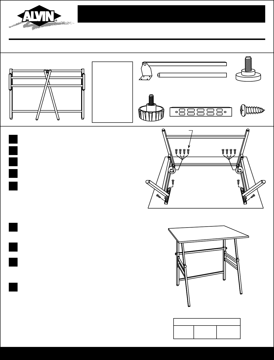
Figure 1
For models X-3-XB, X-4-XB,
X1-3-XB, X1-4-XB, XII-3-XB. XII-4-XB
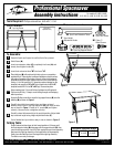
Parts Included:
A 1pc Leg Frame
Unpack all parts and inspect to confirm that all are present.
Unfold base
(
A
)
.
Insert rear extension tubes
(
C
)
completely into frame
(
A
)
and
loosely hand-tighten knobs
(
F
)
.
Insert front extension tubes
(
D
)
into frame
(
A
)
.
Place table top
(
B
)
with preferred side facing down on carpeted or
protected floor. Place supplied cardboard template on board surface
with edge of template at front edge of board. Left and right edges of
template should be an equal distance from each side of the table top.
Using a
1
/16" drill bit, gently drill ¼" deep holes where indicated on the
template (red squares for 24" x 36" top or black holes for 31" x 42";
template marked XB-II is for 36" x 48" top). Remove template.
Wrap masking tape ¼" from drill bit end to determine drilling depth.
Take care to drill only ¼" deep to avoid drilling through and damaging
table top surface.
Using the Phillips screwdriver, screw the leg support braces
(
G
)
onto the
tabletop
(
B
)
as shown in
Figure 1.
Carefully turn table frame upside down and place on top of
tabletop. Align holes in front leg extensions
(
D
)
with holes in table
top as shown in
Figure 1.
Fasten all ½" screws
(
H
)
and tighten
securely. Use care not to overtighten and strip.
Carefully return table assembly to the upright position. Adjust table
top to desired height using height adjustment knobs
(
F
)
.
You’re finished and your table is ready to use as shown in Figure 2.
1
2
TIP
B 1pc Tabletop C 2pcs Rear Extension Tubes
E 2pcs Floor Glides
F 2pcs Height
Adjustment Knobs
H 12pcs
1
/2"
Wood Screws
Figure 2
©2008 ALVIN & COMPANY, INC. • P.O. Box 188, Windsor, CT 06095-0722
Phone: 860-243-8991 • Toll-Free: 800-444-2584 • Fax: 860-242-8037 • Toll-Free Fax: 800-777-2896
www.alvinco.com
LIT-A8002 4/08
½" Screws
To Assemble:
Drop all extension tubes down to their lowest positions. Lift top up until
the front extension tubes
(
D
)
disengage with the support braces
(
G
)
, then
move the left leg assembly in until it is flush against the rear frame assembly.
Next move the right leg assembly in flush against the left leg assembly.
Gently lower the table top down flush against the right leg assembly.
The table is now ready for storage.
G 2pcs Leg Support Braces
3
4
5
6
7
8
Professional Spacesaver Models
X-3-XB
X-4-XB
XI-3-XB
XI-4-XB
XII-3-XB
XII-4-XB
D 2pcs Front Extension Tubes
Folding Table:
(Shipped in
separarate box)