


15
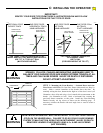
WARNING
TO PREVENT THE RISK
OF PERSONAL INJURY,
DAMAGE TO DOOR OR
PROPERTY, ONLY
OPERATE DOOR
CONTROLS WHEN DOOR
IS IN CLEAR VIEW. KEEP
REMOTE CONTROL
AWAY FROM CHILDREN
IN SECURE AREA.
104386
D:
AUXILIARY EQUIPMENT
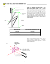
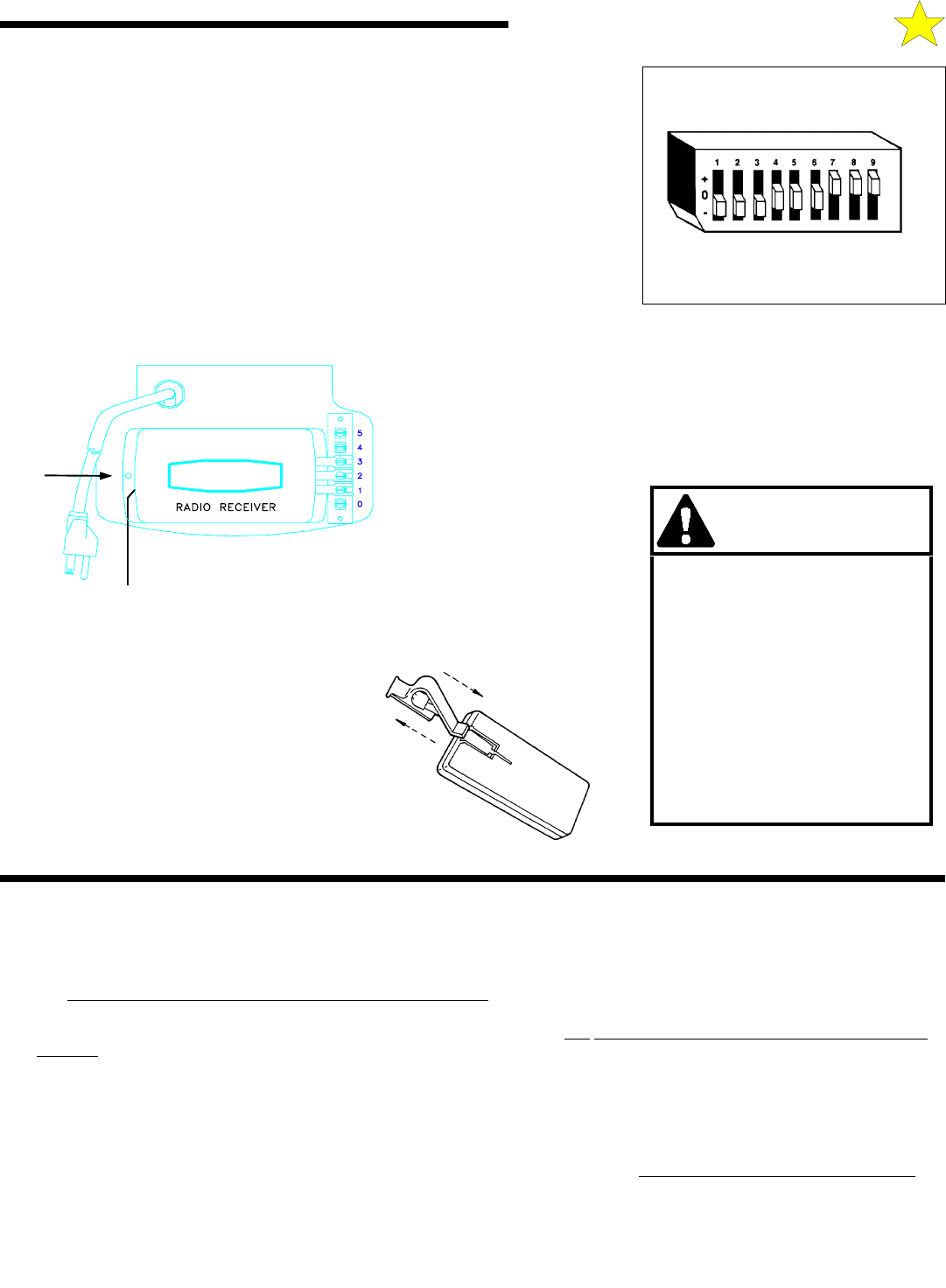
Setting The Coding Switches: When setting the Coding Switches THE FACTORY
PRE-SET CODES MUST BE CHANGED TO PREVENT UNAUTHORIZED
OPERATION. Transmitter and Receiver codes must be set IDENTICALLY. If just
one Code Switch is mismatched, the Radio Controls will not function.
NOTE: For security reasons, it is advisable NOT to set all the switches in the
same position.
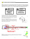
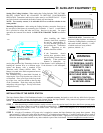
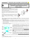
Mounting The Receiver: After setting the Coding Switches, mount the Receiver on
the rear panel of the Opener by connecting it to Terminals 1, 2 and 3. A small Plastic
Pin is provided to secure the other end of the Receiver to the panel. For proper
operation, the Antenna Wire should be POINTED STRAIGHT DOWN toward the
floor.
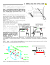
After installing the Radio
Controls, check their operation
by moving approximately 35
FT away from the garage door
and pressing the Transmitter
Button. Operation at this
distance should be reliable.
If the Transmitter doesn't
activate door operation, check
that all Coding Switches are set
identically. If the operational
distance is inadequate, try
moving the position of the Transmitter in the car. If the distance is still inadequate, try
bending the Antenna Wire to a different angle. If the distance is still inadequate,
replace the Battery with a standard 9-Volt
“transistor radio” Battery (NEDA 1604). The
Battery is located in the front compartment next to
the Coding Switches.
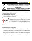
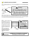
The Transmitter may be hand held if desired by
removing the Visor Clip from the rear of the Case
as illustrated. Place your finger in the loop at the
top of the visor, and your thumb on the top edge
of the Transmitter. Push down with your thumb
and pull up with your finger. The clip will release
and pull out easily.
CODING BLOCK: Transmitter and
Receiver Coding Switches are contained
in identical Coding Blocks, consisting of
nine small switches, labeled 1 - 9, each
of which can be set in any of three
positions, labeled +, 0, -
POINT ANTENNA
STRAIGHT DOWN
PLASTIC
PIN
108386
104388
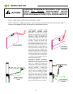
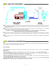
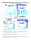
INSTALLATION OF THE SUPER STATION
The Super Station (Deluxe Wall Pushbutton Station) is an optional accessory designed to work with any 6000 Series Operator.
Connection to any other operator may damage the operator and/or the Super Station. Only connect one operator to each Super
Station. Do not connect more than one Super Station to an Operator.
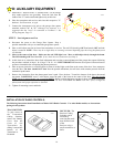
STEP 1:
After determining a suitable location, usually near the access door and at least 5 feet above the floor to prevent use by
children, use the Super Station as a guide to mark the mounting holes. Drill holes for drywall anchors or screws. NOTE: Do
not mount directly to masonry walls. Use backer board. The Super Station is also designed to be mounted directly to a
standard single electrical box.
STEP 2:
A length of 2-conductor, #22 gauge wire is required to connect the Super Station to the garage door operator. Strip
approximately 6” of the wire jacket from one end and 1/2” of insulation from each wire. Carefully connect one wire to each of
the two terminals indicated, noting which color is connected to which terminal. Tighten screws, being careful that no wires are
allowed to touch any other terminal or any other conductive part of the circuit board. Do not overtighten the terminal screws.