


®
© 2005 595-5753-05
3. Testing
1. Installation
2. Aiming
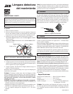
Figure 2 - Coverage Angles
110°
8 Ft.
60 Ft.
From House
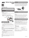
Figure 1 - Wiring at Junction Box Plate
Motion Sensing
Light
White to white
Black to black
Connect the fixture ground wire
to the junction box ground wire.
Specifications:
Total Lighting Wattage .................Up to 150 Watts Maximum
Range ...........................................Up to 60 ft.
Time Delay ...................................1, 5, or 10 minutes
Replacement lamp ........................T3, Up to 150 Watt Maximum
halogen 120 VAC
Caution: This product is to be used with a U.L. listed rain tight
or wet location suitable outlet box. Depending on the installation,
additional hardware may be required.
Note: Installation of this light control should be done only by those
with experience in 120 Volt household wiring. Some local codes
may require that a licensed electrician install the light control.
Model 3108685 / 3209574
Caution: Always turn the circuit breaker off when wiring
the fixture.
1. Remove the existing fixture.
2. Knockout the mounting plate holes needed to mount the sensor
on the junction box.
3. Connect the light control as shown in Figure 1:
• Black sensor wire to the black (HOT) house wire.
• White sensor wire to the white (NEUTRAL) house wire.
4. Attach the junction box cover plate to the junction box. Use a
weatherproof sealant to seal the plate to the junction box.
5. Adjust fixture. The lamp head should be at least 1 inch away
from the sensor.
The sensor must be mounted below the lamp housing for wall
installations.
Caution: Do not mount the sensor above or touching the lamp
(keep 1 inch or more from the lamp). The sensor bottom must be
facing down for best coverage and to avoid water damage and
electrical shock.
CAUTION: To Avoid Fire Or Burn Hazards:
• Allow fixture to cool before touching. The bulb and the fixture
operate at high temperatures.
• Keep fixture at least 1" from combustible materials. Do not aim
at objects closer than 3 ft.
• Use only T3, 150 Watt (Maximum) tungsten halogen 120 VAC
lamps.
Note: For under-eave installation, rotate the sensor head 180° by
bending the sensor towards the clamp bracket. Rotate the sensor
bottom clockwise away from the bracket.
The coverage area for the sensor is shown in Figure 2. The sensor
should be aimed so that the motion to be detected is in front of and
across the coverage area. The sensor should be aimed looking out
at a horizontal angle. To reduce false triggering, point the sensor
away from traffic areas, air conditioners, dryer vents, water pools,
or anything which may move or change temperature rapidly.
For motion sensing, put the ON-TIME switch on the bottom of the
sensor in the 1, 5, or 10 minute position. When motion is detected,
the lights will come on the selected time.
Note: The photocell keeps
the lights from turning on in daylight.
To keep lights on all night, flip the light switch off for 1 second
then back on. Turning the light switch off for 1 second, then back on
again will return the control to the motion sensing mode. At dawn,
the control will reset to the motion sensing mode and shut off.
This light control automatically turns the light on when motion is
detected.
4. Operation
Turn the power back on at the circuit breaker. Turn the light switch
on.
Note: When first turned on wait about 1
1
/
2
minutes for the circuitry
to calibrate.
Put the TIME switch on the bottom of the sensor in the TEST position.
You can now walk in front of the unit and the lights will come on for
about 5 seconds. The TEST mode works both day and night.
Walk through the coverage area and point the sensor to obtain the
desired coverage area. Adjust sensitivity as needed.